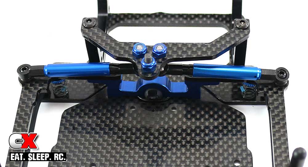
The Build – Part 4
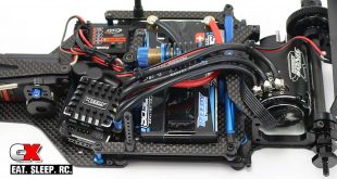
The rear suspension on the Team Associated Factory Team F6 uses a floating pod system. A center shock, links and side dampers control movement through the corners. The center pivot is usually the weak point of the rear pod but, unlike alot of other cars, this one looks to be pretty tough!
 There are quite a few parts that are directional in this step. I’ll point them out individually but wanted to add this as a heads up in case you don’t read the step notes.
 Steps 13 and 15 show assemblies with screws that appear too long. This is not the case; AE has an interesting way of attaching the center shock using these longer screws. We’ll get to that later.
 Threadlocker is used in Part 4 of the build as well. I’m not going to call it out in every step, but if a screw is going into aluminum, it’s best to add a dab of the blue stuff.
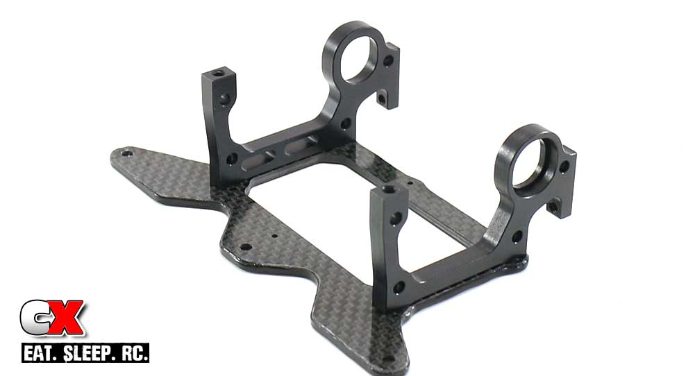
Let’s start this step by attaching the left and right aluminum bulkheads to the lower pod plate. Note the orientation of the rear axle inserts.
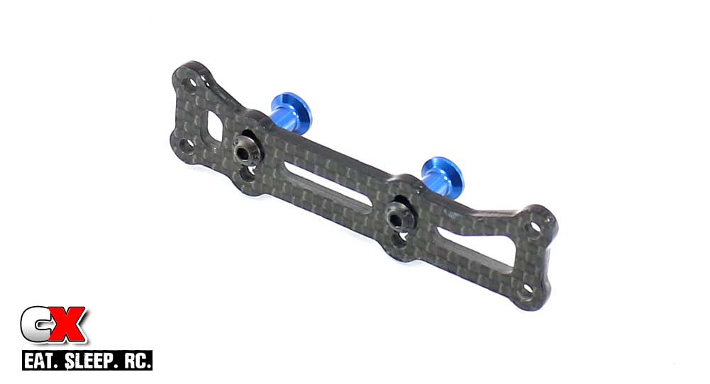
Assemble the rear motor mount brace. This is directional, so make sure the it’s built as shown.
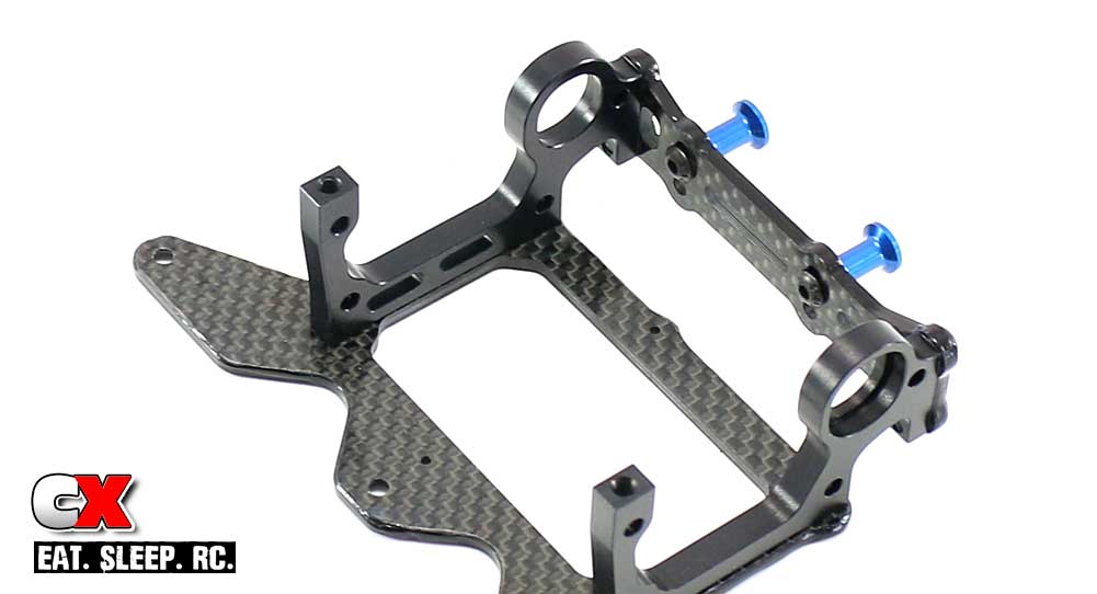
Once built, attach the motor mount brace to the aluminum bulkheads.
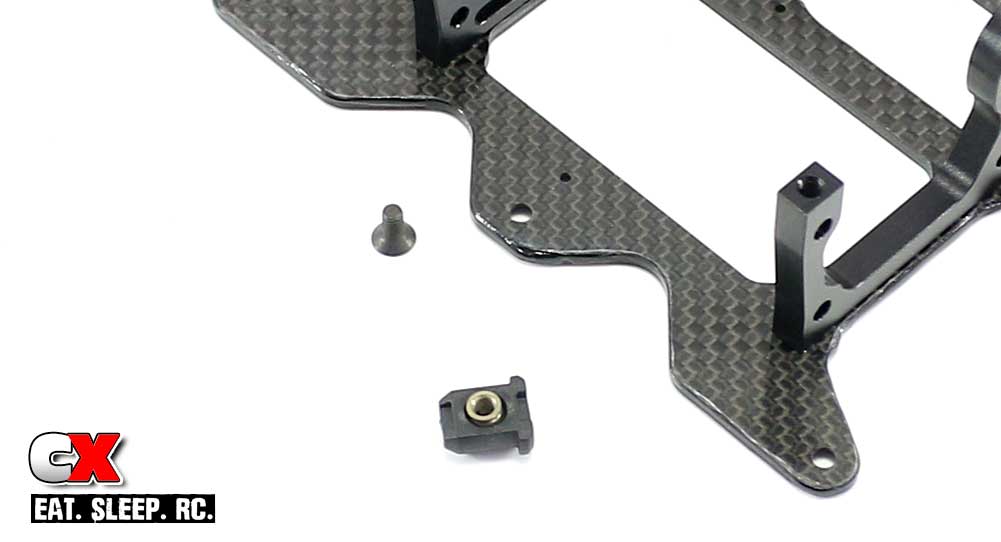
Pop one of the Factory Team pivot balls into the pivot brace slider and attach to the rear pod.
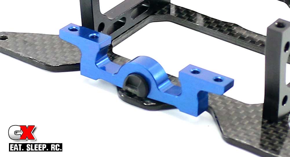
Rotate the slider from Step 4 so that the pivot brace slides on from the front of the pod assembly.
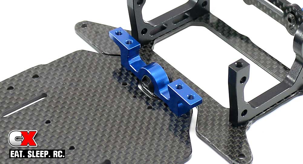
Attach the pivot brace to the main chassis.
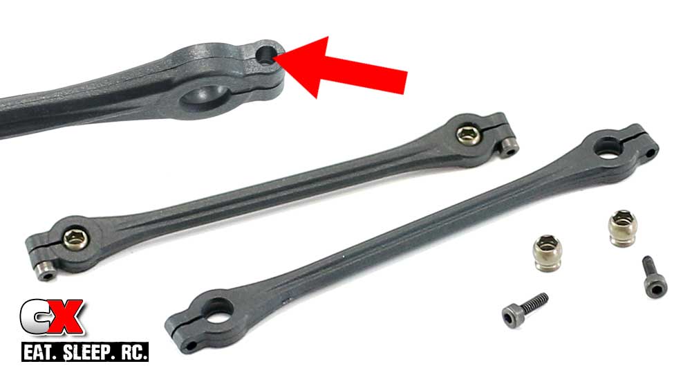
Building the side links is next. Start by popping the Factory Team pivot balls into the pod links.
Now, before inserting the screws, take a look at the holes on each link (see red arrow). One side has a larger hole that the other; the 2x6mm screws goes into this large hole FIRST. Slowly tighten it down until it pinches the FT pivot ball, then back it off slightly. You want it tight but not hindering the movement of the ball. Build 2.
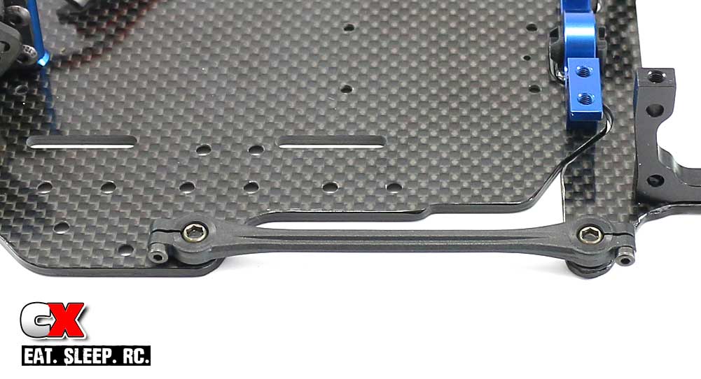
Attach the links to the chassis. Note the orientation of the links based on the 2x6mm screws.
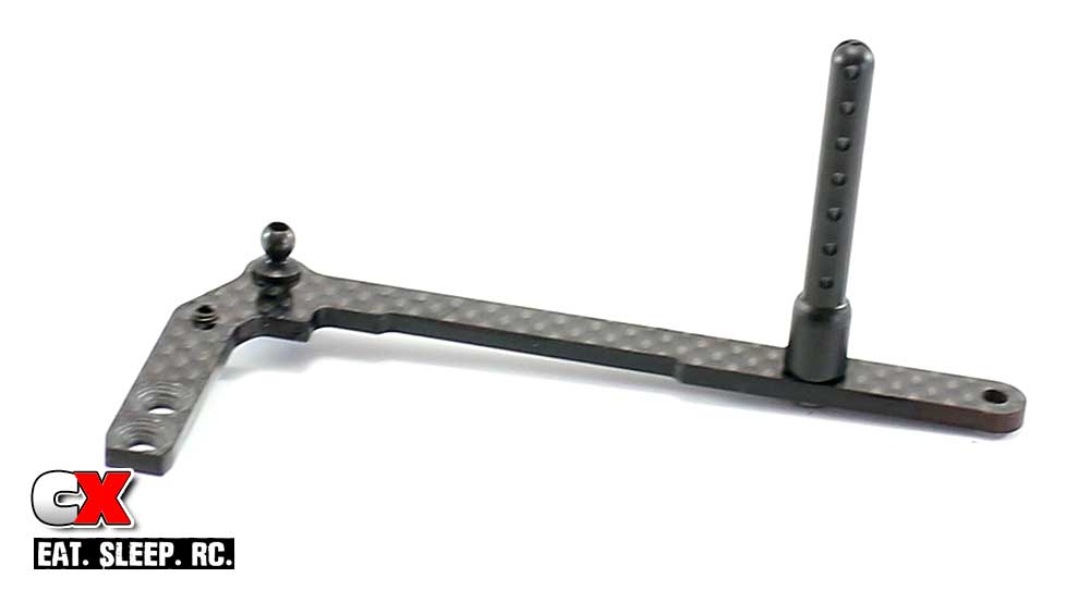
Assemble the left and right chassis braces. Tighten the setscrew until at least 3/4 of it is below the brace.
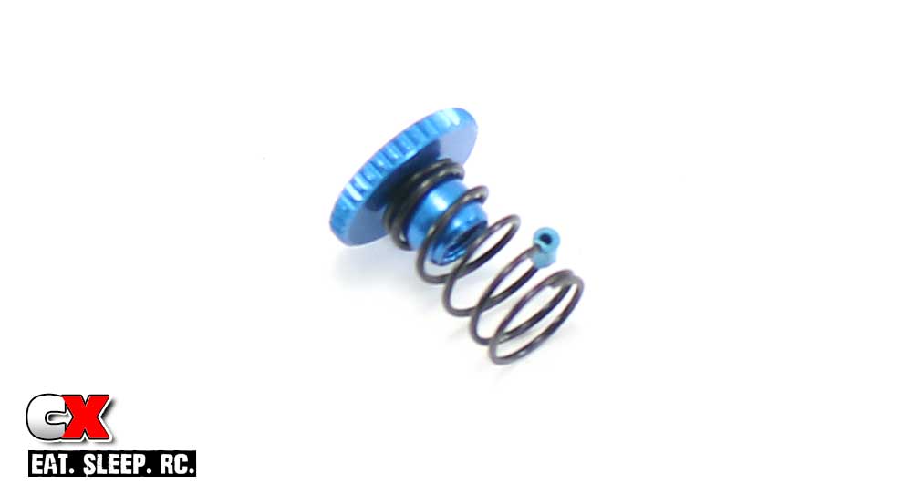
The side spring is designed to ‘pop’ onto the side spring retainer as shown. Make 2 of these.
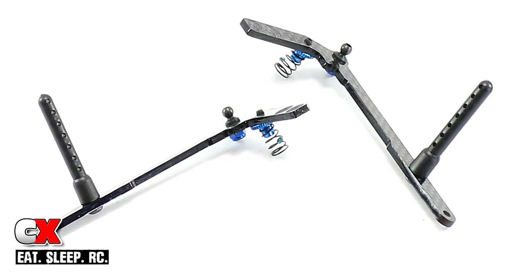
Screw the side spring retainers onto the setscrews. Your final side braces should look like this.
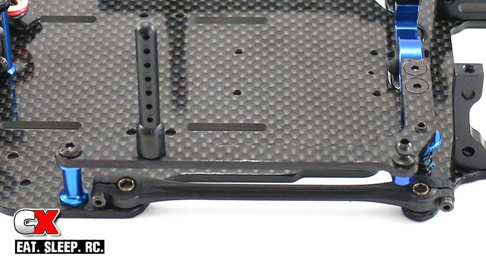
Attach the pair of standoffs to the chassis followed by the chassis braces.
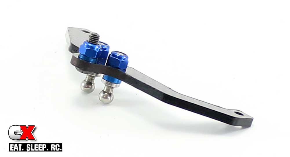
Assemble the rear upper pod plate. Again, don’t worry about how odd the 3x10mm screw looks.
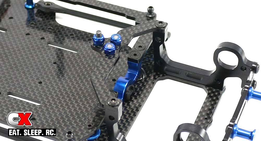
Attach the upper pod plate assembly to the rear bulkheads.
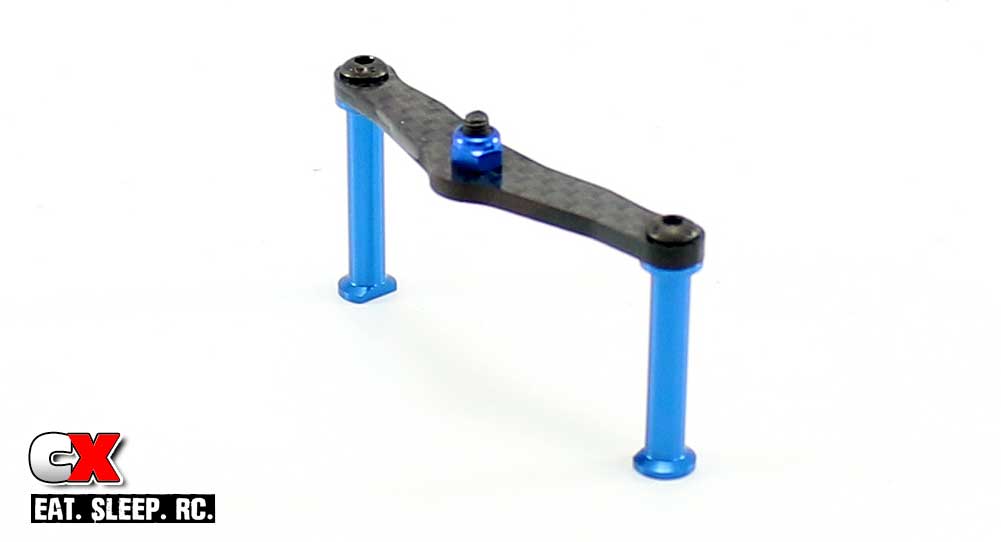
Assemble the shock mount. Note the feet of the standoffs; the flat parts should be facing each other.
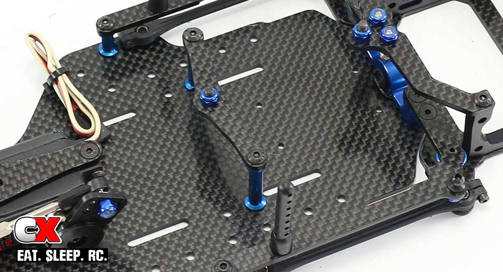
Attach the shock mount assembly to the chassis.

Finally, attach both damper tubes to the mounting locations.
Give the rear suspension a good wiggle; it should feel free with no binding. If you feel some notchiness or binding, head back up to Step 1 and make sure you assembled everything correctly.
On to the rear axle!
Team Associated Factory Team F6 Build – Opening Page
Team Associated Factory Team F6 Build – Part 1 – Shock, Damper Tubes & Turnbuckles
Team Associated Factory Team F6 Build – Part 2 – Front Suspension & Servo
Team Associated Factory Team F6 Build – Part 3 – Steering
Team Associated Factory Team F6 Build – Part 4 – Rear Suspension
Team Associated Factory Team F6 Build – Part 5 – Rear Axle
Team Associated Factory Team F6 Build – Part 6 – Wings
Team Associated Factory Team F6 Build – Part 7 – Electronics
 CompetitionX CompetitionX is the most up-to-date source for RC Car News, Reviews and Videos for Radio Control. We also have the most comprehensive Manual Database on the web.
