
Beginner’s Guide to RC – Change Connectors on Your Battery and ESC
One of the ways manufacturers help keep costs down is to supply their batteries and ESCs with inexpensive connectors. On the plus side, these connectors can cost fractions of what the good, high end connectors cost, allowing them to pass that savings down to you. Because these connectors are so inexpensive, it also makes them massively abundant when it comes time to buy additional batteries or upgrade to a new ESC. In addition, most chargers come with at least one type of these connectors.
These connectors can have a pretty substantial downside, however. When powering your RC car or truck, the juice from a battery flowing through the wires to the ESC can generate heat. This heat can cause two problems: 1) The heat is basically wasted power and can be a reason your vehicle seems slow. 2) This heat can melt the connectors, fusing them together and potentially causing a serious situation (ie, fire!).
Changing to a good, quality set of connectors is a cheap way to both reduce heat (providing more power) and help prevent a meltdown that could destroy more than just your vehicle.
In this How To, we explain how to change the connectors on your ESC. The same steps apply when changing the connector on your battery, however you’ll want to take these additional precautions:
1) When removing the connector from your battery, DO NOT cut both wires a the same time. Doing so could create a bridge that WILL create a pretty spectacular spark. Cut one wire, bend it out of the way and cut the second wire.
2) Make sure you attach the wires to match the connnector on the ESC. If you attach them backwards and plug it into the ESC, you’ll be in for a big, smokey surprise when you turn your vehicle on.
For a explanation on the most common connectors in RC, check out this page: Battery Connectors and Balance Plugs Explained
That’s about it, let’s get on with the How To.
1. Tools Required
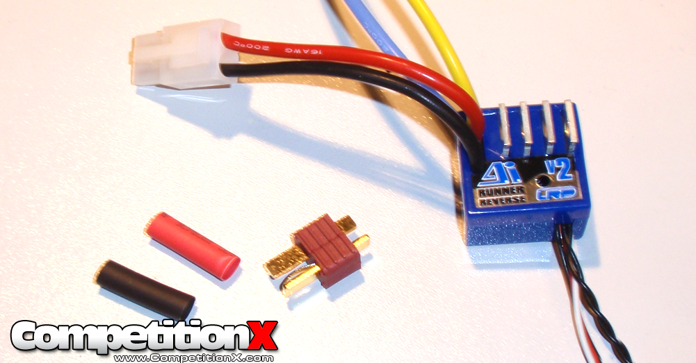
To change the connectors, you’ll need your ESC (or battery) with the not-so-great connector. You’ll also need a new set of connectors, shrinkwrap (color-coded is suggested), a soldering iron, solder and something to clip the wires with (scissors, side-cutters, hobby knife, etc).
2. A Set of Helping Hands
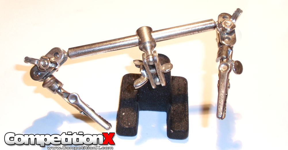
I would suggest, if you think you might be soldering quite a bit, to pick up one of these Hobby Tools Helping Hands Soldering Aid. This thing works great for holding wires and connectors while soldering.
3. Snip the Tip
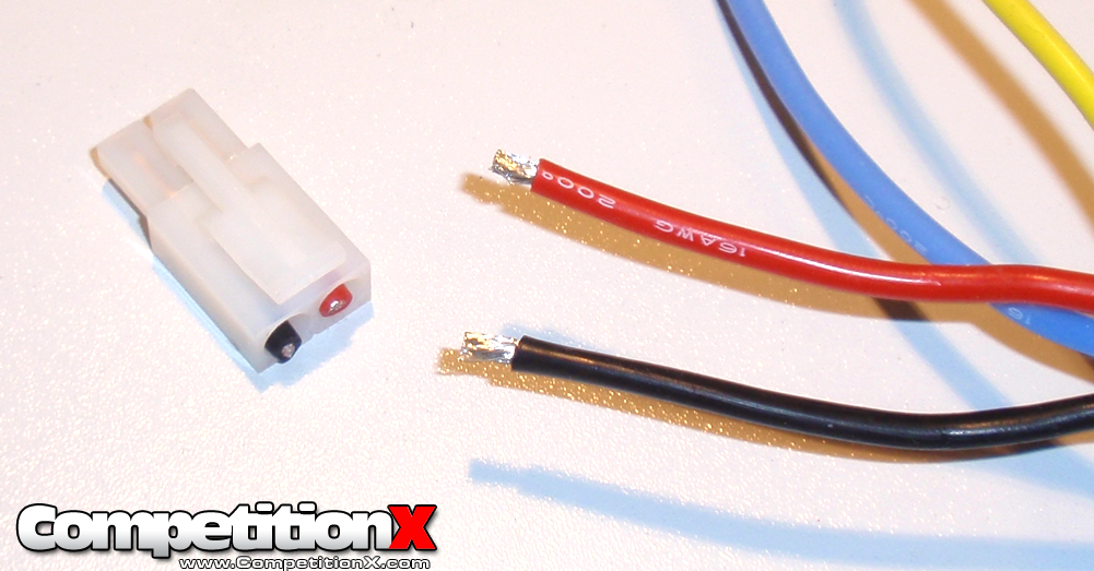
The connector pictured is extremely common and referred to as a Tamiya connector, one of the most widely used connectors in RC. Snip that connector off and toss it in the trash. Take your scissors (or hobby knife, or whatever) and trim a small amount of the shielding off of both wires as shown. If you are working on a battery, trim the shielding off of one wire and fold it out of the way before working on the second wire. If you are changing the connector on a battery, DO NOT LET THE EXPOSED WIRES TOUCH! If you’re still concerned, wrap a piece of tape over the wire and proceed to the second wire.
4. Prep Your Wires
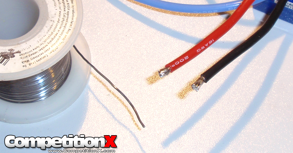
Tin both wires with a little bit of rosin-core solder as shown. Make sure to coat the wires completely.
5. Check the Connector
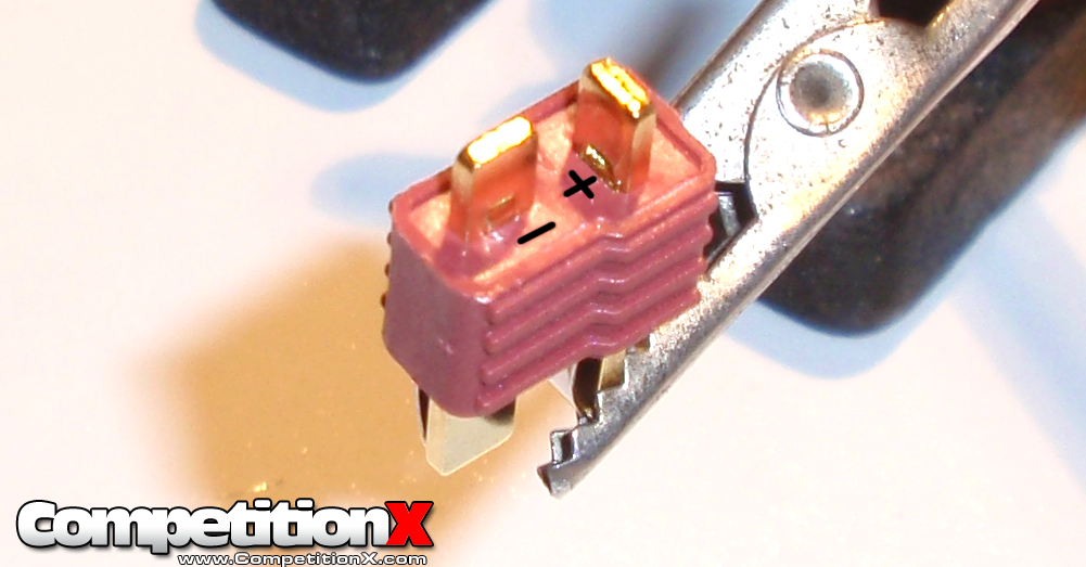
All high-end connectors have the positive and negative terminals designated on the connector itself. You want to inspect the connector carefully to make sure you’re solding to the correct terminals. This Deans-style connector has the + and – near the tabs themselves; I’ve highlighted them in black so you can see them better.
6. Tin the Tabs
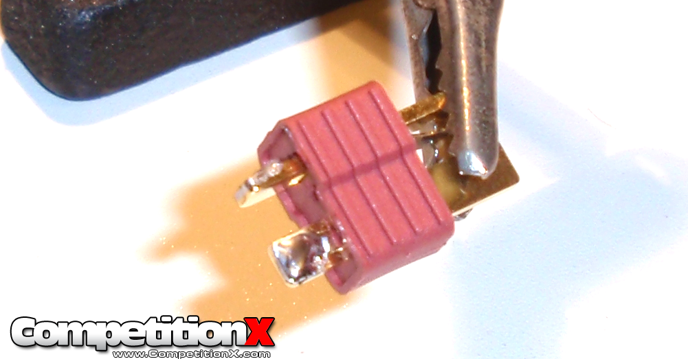
Apply a small amount of solder to the tabs on the connector.
7. Final Soldering
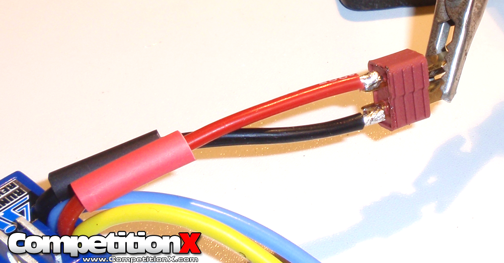
Slide a piece of shrink tubing onto each wire (I use Reedy’s pre-cut #650 Shrink Tubing). Carefully solder each wire to the new connector, again making sure you attach the red wire (or positive wire) to the + terminal (positive terminal) and the black wire (negative wire) to the – terminal (negative terminal). You can see so far how handy the Hobby Tools Helping Hands Soldering Aid is!
8. Seal the Solder
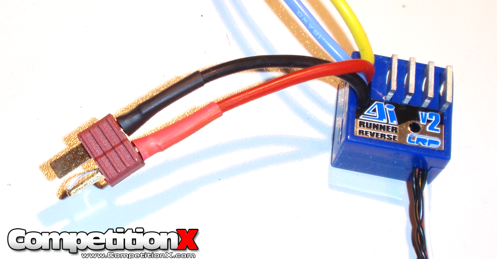
Slide the tubing down and over the connector terminal and use a heat source to shrink it to size. You can use your soldering iron, lighter or even a hair dryer. Just be careful not to burn yourself.
So there you have it, eight easy steps to change your connectors out. Your electronic system will waste less energy, your car will have more power and your connectors will make you look like a Pro. Great job!
Here are links to the suggested tools in this article.
Soldering Equipment
Solder
Helping Hands
Upgraded Connectors
Heatshrink
Scissors
 CompetitionX CompetitionX is the most up-to-date source for RC Car News, Reviews and Videos for Radio Control. We also have the most comprehensive Manual Database on the web.


Deans are great connectors for the system. I used TRX connectors and I hated it for so many reasons. First of all, the soldering part was the most difficult soldering I ever had to do.
When I applied the solder on the connector, I found that I could not go over that little line on the connector that says “no solder”
I eventually went over the line and it caused me a great deal of headache because it did not FIT in the plastic housing. No matter what I did it just didn’t go in! I kept braking my solder and solder again and again to get it perfect but that only caused me to coat the whole connector with the solder. It was a nightmare and I have soldered other connectors very well in the past.
So I took it to the local hobby shop “hobbypeople” and paid them 5 bucks to solder that TRX connector to my ESC. AND Man they struggled hard as well. One guy tried to put that connector inside the plastic housing by putting a lot of pressure with the flathead screwdriver. I was a bit afraid that the screw driver will pierce his fingers. (He said it happened previously and told me not to worry about it).
At the end of the day, we both agreed it is a terrible design flaw and he would not recommend TRX connector to anyone. I had to get it fit because all my gears (charger, battery) are in traxxas connectors.
Try Deans like Tony showed if you have the option and save the hassle!
Deans all the way. Easy, simple and inexpensive.